8 Bit Parity Generator Circuit Diagram Digital Circuit And K
Vhdl tutorial – 12: designing an 8-bit parity generator and checker Solved: parity generator design, construct, and test a circuit that Parity checker interpretation boolean algebra
Figure 1 from 3-bit Digital Electro-Optic Odd Parity Generator based on
Truth table and interpretation of a 3-bit parity checker Parity checker bit vhdl circuits Parity checker generating
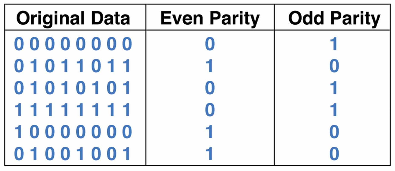
Parity bit odd generator checker even circuit
8-bit parity generator circuit diagramParity generator (8+2 bit) Implementing a binary parity generator and checker with greenpakParity vhdl checker.
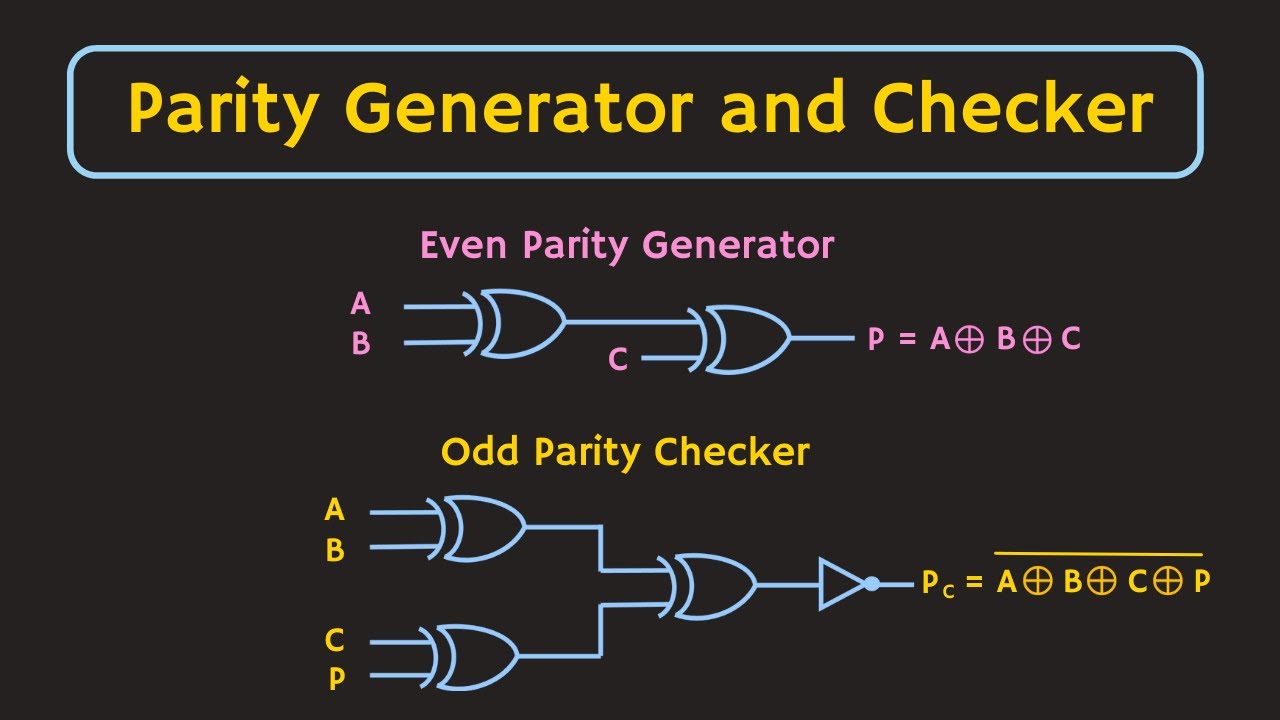
Digital circuit and k-map of a three-bit-odd-parity generatorParity schematic proposed Parity generator and checker circuitParity generator and parity checker : logic circuits and their types.

8 bit even parity generator vhdl code
Vhdl tutorial – 12: designing an 8-bit parity generator and checkerVhdl tutorial – 12: designing an 8-bit parity generator and checker The proposed 8-bit even parity generator (a) schematic, (b) circuitParity bit- even & odd parity checker & circuit(generator).
Even parity generator circuit diagramStep by step method to design a combinational circuit – vlsifacts Parity generator diagram logic checker binary bit odd figure parallel table[diagram] circuit diagram 3 bit parity generator.
Parity odd
8 bit parity generator circuit diagramParity generator bit bits gate 4x4 array multiplier informatik level Parity logic generator odd checker circuit diagram types diagrams itsQca implementation of the proposed 8 bit parity generator circuit.
Parity checker vhdl circuitsParity generator and parity checker circuits Parity generator and parity checker[diagram] circuit diagram 3 bit parity generator.

[diagram] circuit diagram 3 bit parity generator
8-bit parity generator circuit diagramParity generator and parity checker [diagram] circuit diagram 3 bit parity generatorFigure 1 from 3-bit digital electro-optic odd parity generator based on.
[diagram] circuit diagram 3 bit parity generator8-bit parity generator circuit diagram Circuit diagram 3 bit parity generatorLogic diagram of 4-bit even parity generator.

Parity checker odd technobyte
8-bit parity generator circuit diagramParity generator odd Truth table generator digital logic – two birds homeParity generator checker circuit.
Design a 4 bit odd parity generatorCircuit parity generator even combinational step method The four-bit parity generator and checker circuit.

Even Parity Generator Circuit Diagram

Parity Generator and Parity Checker

Truth Table Generator Digital Logic – Two Birds Home

Circuit Diagram 3 Bit Parity Generator

Figure 1 from 3-bit Digital Electro-Optic Odd Parity Generator based on

8-bit Parity Generator Circuit Diagram
.jpg)
Implementing a Binary Parity Generator and Checker with GreenPAK - LEKULE